Assignment: Design a self-balancing robot using IMUs. The robot must rotate freely and be inherently unstable (does not self-balance).
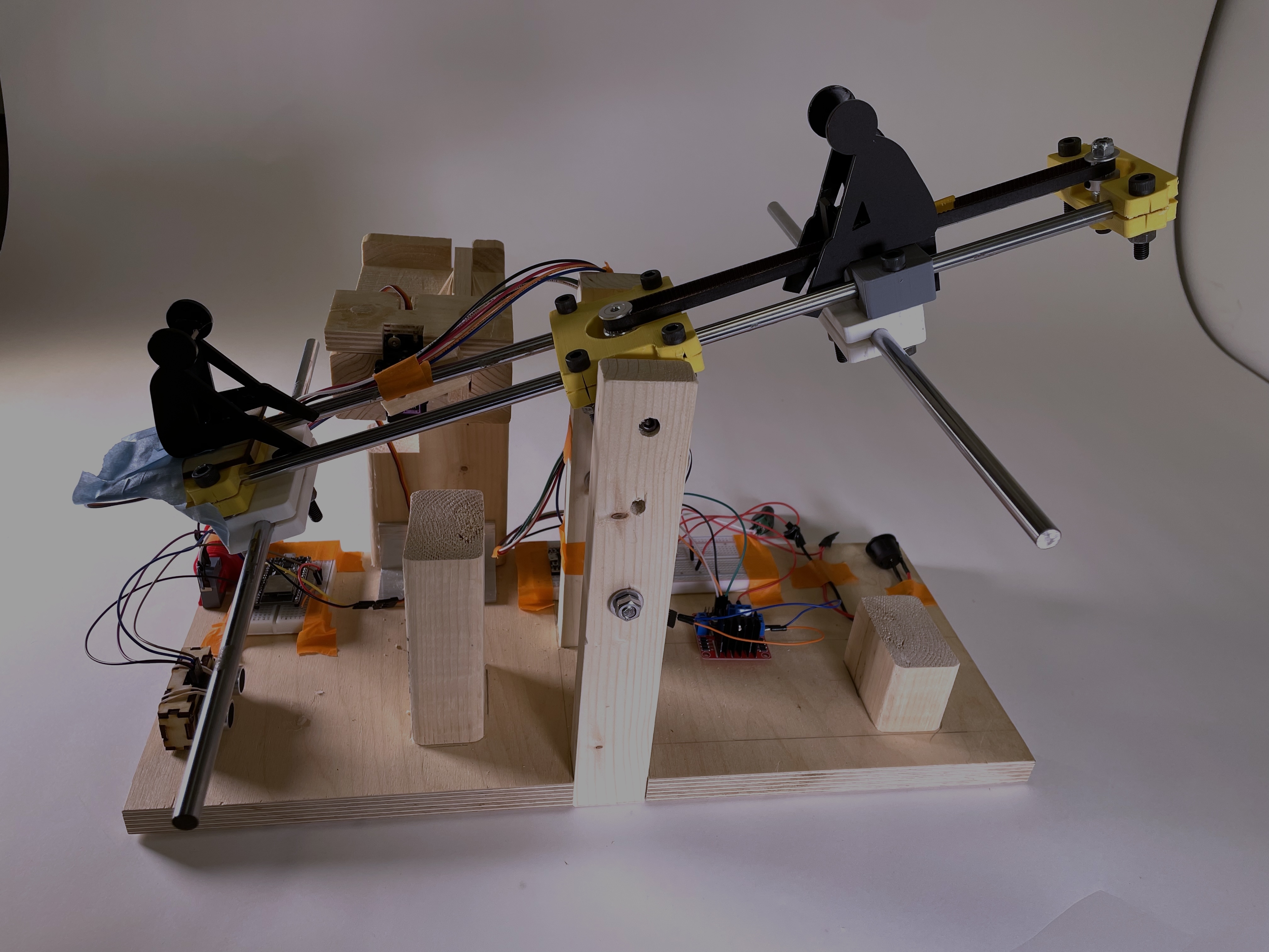
For this assignment, my partner and I stepped away from the traditional two-wheeled self-balancing robot, and challenge ourselves in both the mechanical and control areas. We decided on a stationary robot that would shift its center of mass by way of moving a weight along rails. The result was a robot that would oscillate about its pivot point, like a seesaw.
Potential applications of a scaled up version of this design include construction equipment or products used for other lifting purposes.
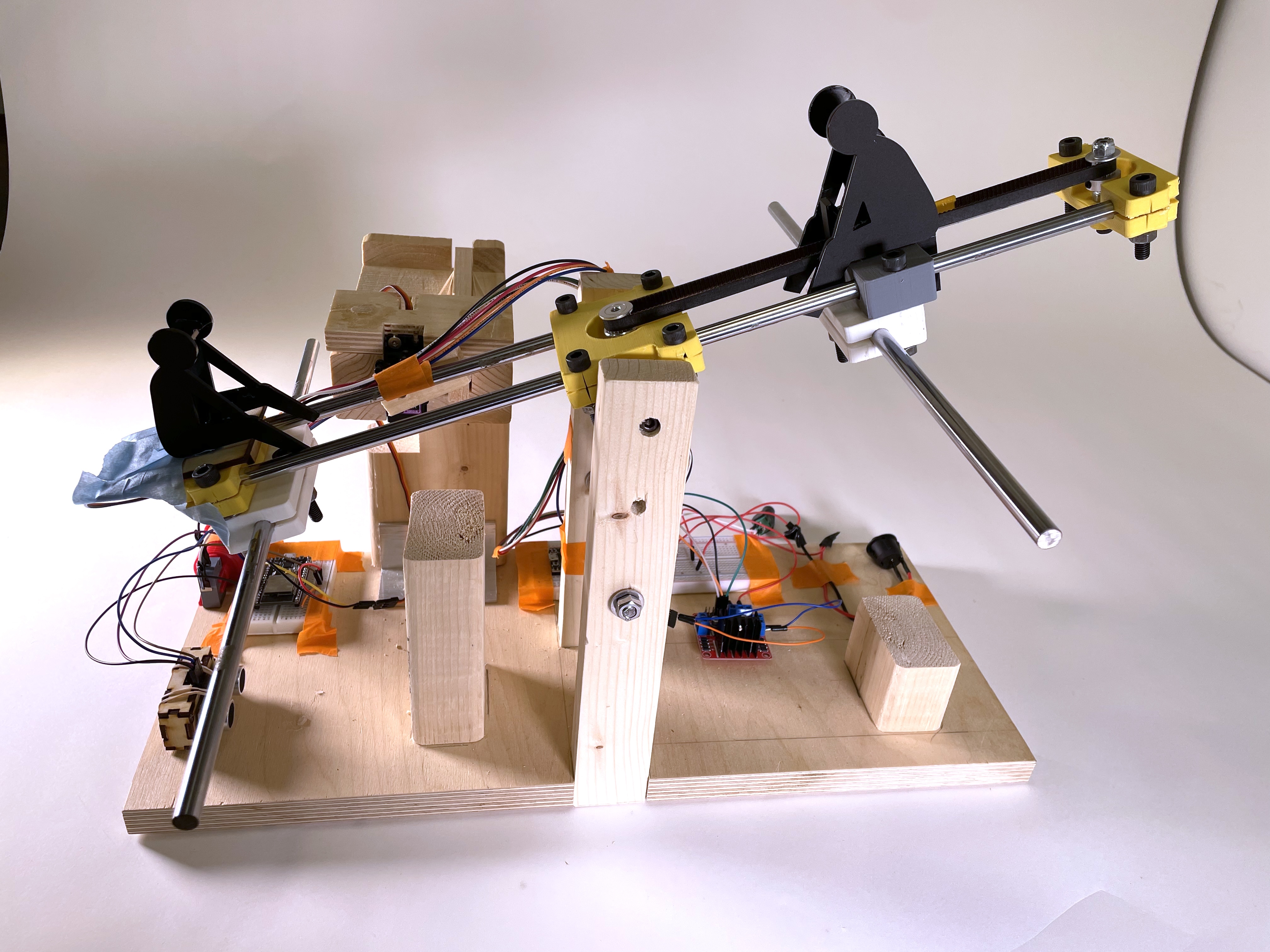
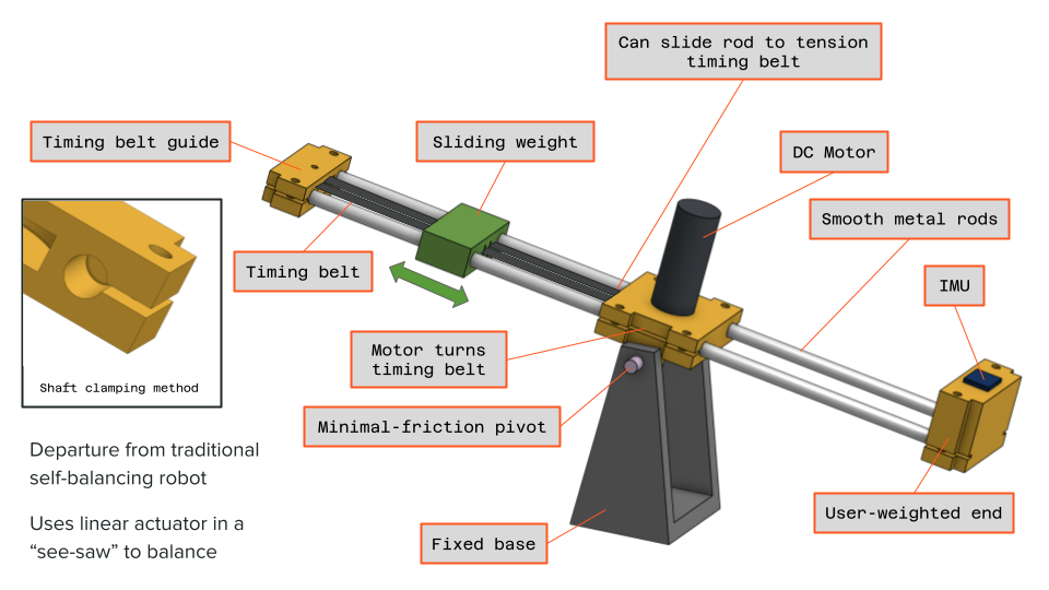
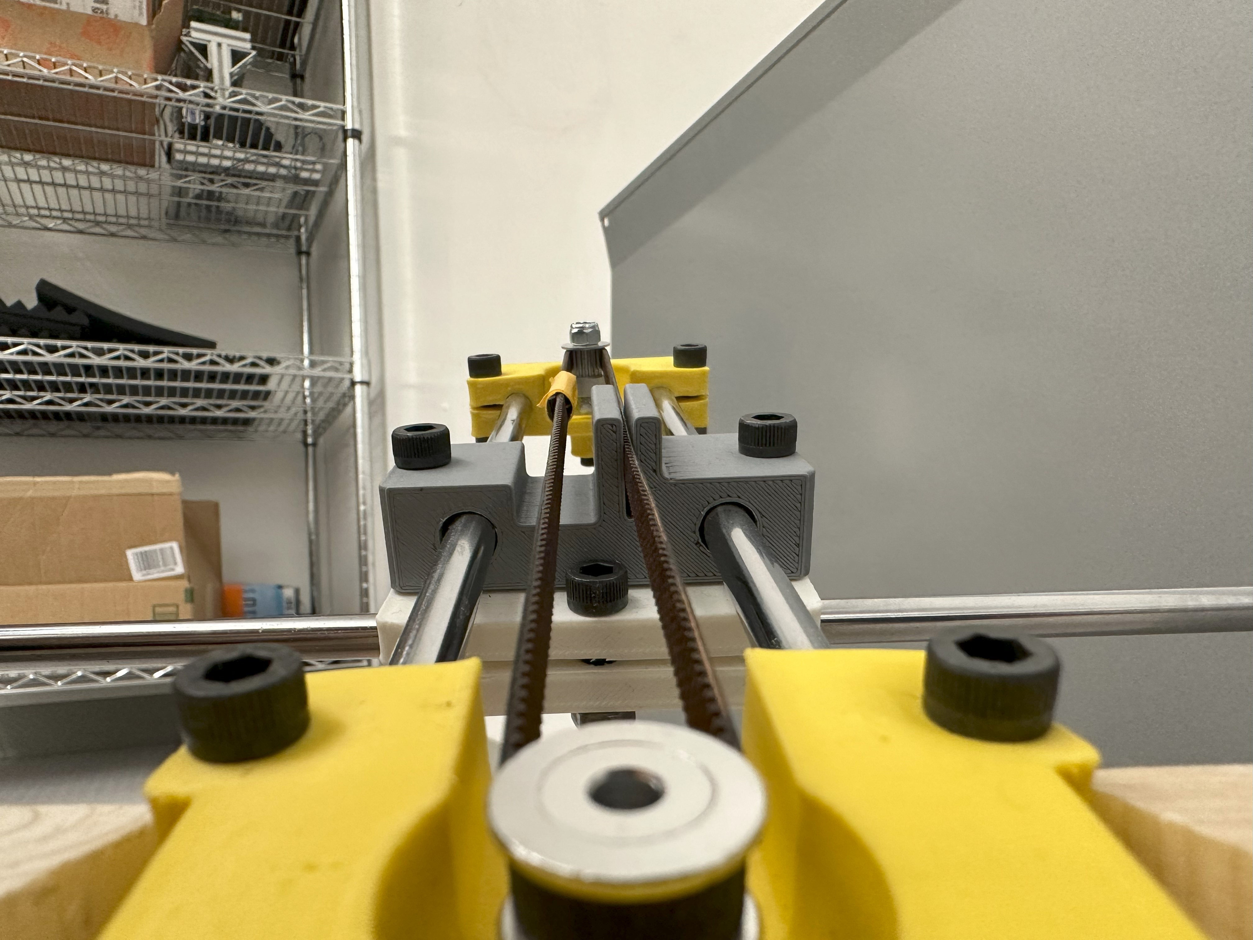
Below is a labeled diagram for the components of the robot. The robot was built around two smooth steel rods that we found to use as rails. To actuate the moving of the weight, we designed a belt pulley system powered by a single DC motor (600 rpm) placed directly above the pivot point. The rotating components were all 3D printed, while the base was made out of wood.
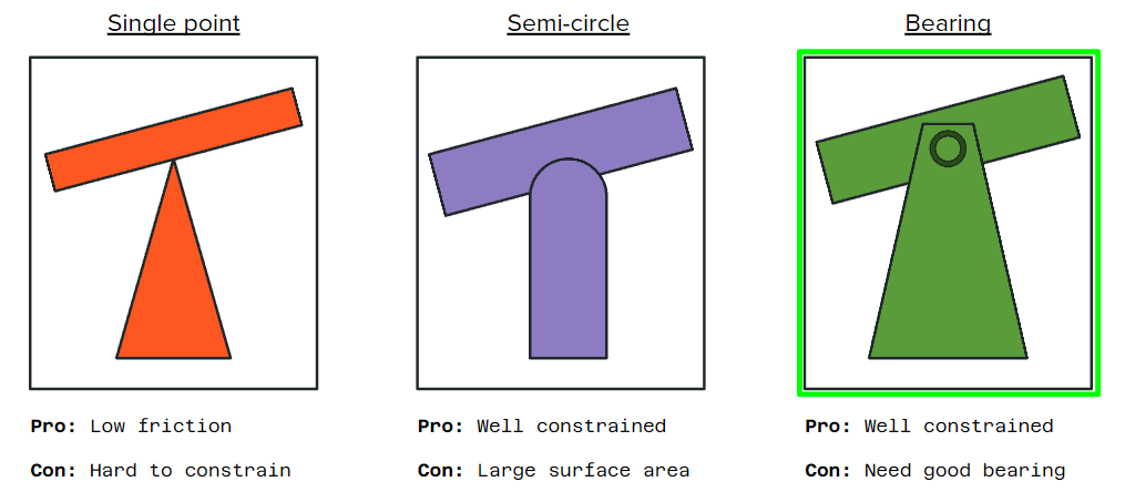
During the initial brainstorming, one hurdle we had to overcome was how to make the pivot point as frictionless as possible. We considered various methods of geometrically constraining the "seesaw". A single point of contact would have led to almost no friction at all, but there was no frictionless way to constrain it that we could think of. A semi-circular contact point would have constrained the mechanism beautifully, but at the cost of a lot of surface area, and therefore a lot of friction. At last, we decided to use a tradional bearing system, but made sure to hunt down some smooth ones.
The initial CAD design is shown below. There were some aspects of the design that were later changed. For example, the DC motor was moved to be below the rails instead of above. This is because the rails were mounted slightly above the pivot point, and mounting the motor below would bring the center of mass slightly closer to the rails, making the system slightly easier to balance. Another design change was the later addition of steel rods as weights. Due to the size of the system, the weights needed to move the center of mass around the pivot point turned out to be a lot heavier than we initially expected.
To make the pulley system, we ordered a timing belt and pulley off of McMaster-Carr and designed the weight mount to clamp on the belt on one side while letting the belt pass through the other side freely.
To control this system, we initially implemented a purely proportional (P) control. However, this led to large fluctuations and angular accelerations that the robot was not fast enough to correct for. After adding a derivative (D) control, the PD controller worked a lot better, as it was able to correct itself before losing control with much smaller oscillations. Due to time constraints, we were unable to implement the integral (I) aspect of the control system, which would have improved the balancing even more. A diagram of the code flow is shown below.
As an additional challenge, we decided to integrate a safety mechanism meant to simulate what would be used if this were to be scaled up and used for construction purposes. If a person were to walk underneath one end of the seesaw, the ultrasonic sensor would detect them, and an elastic-powered safety block would be shot into position to protect the human. This release mechanism was made purely out of wood, a simple servo, and a rubber band.

