Independent Mechanical Engineering masters research project mentored by Professor Felix Huang.
Mission: Design and fabricate a mechanism to interact with a 10mm DC motor with a 1mm shaft. The end goal is to create a class-friendly kit for students to use in their introductory projects.
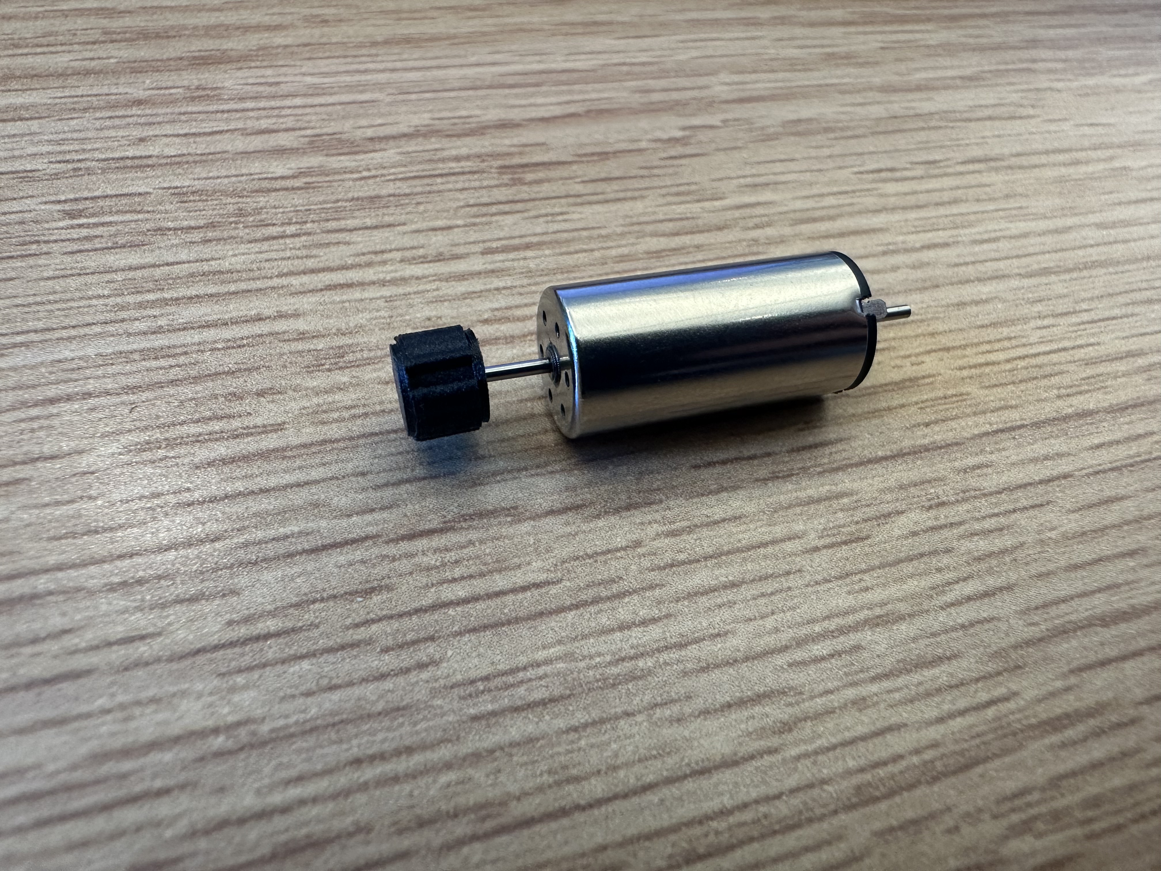
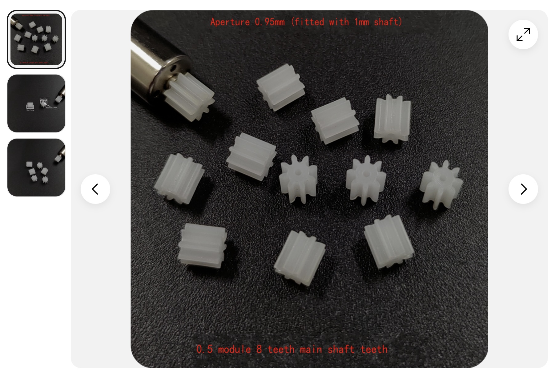
- Mechanism must be cost-efficient and fast to mass produce (meaning no specialized hand tools) - Fabrication must accomodate for the high tolerances and inconsistencies of hobby 3D printers. - Mechanism must be backdrivable to practice safe engineering design - Avoid the friction and deadzone caused by geared systems and belt drives The motor used is shown below:
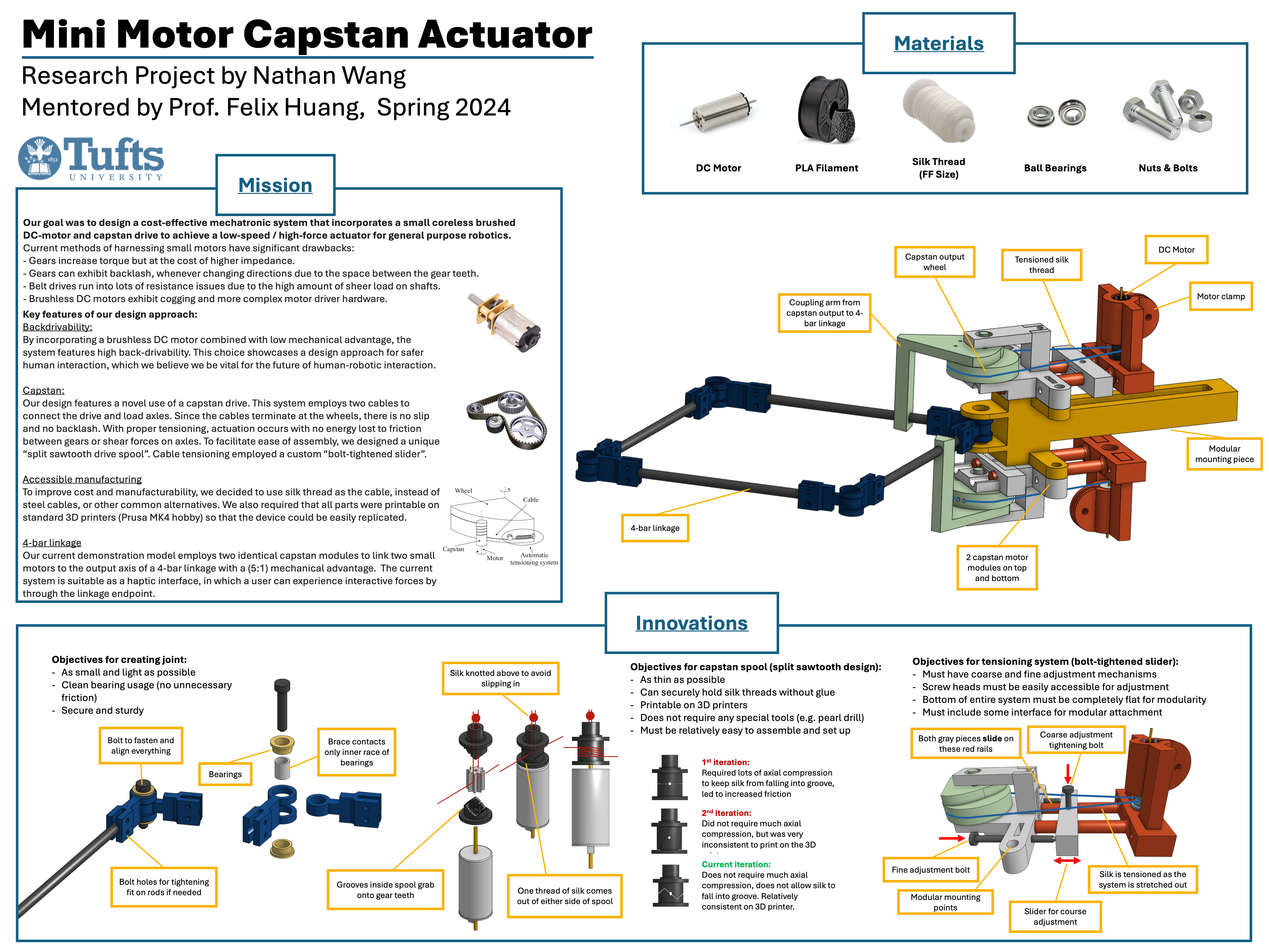
End-of-semester Poster Presentation
Below is the poster I presented for the end of the semester, along with a video demonstration
Weekly Documentation
Week 1
Some general ideas were hammered out during my first meeting with Professor Huang. We decided to design a capstan system to interface with the 1mm motor shaft, as this is likely the most efficient way to use such a small motor without introducing excessive friction or instability. As the motor shaft is currently cantilevered, we talked about including a bearing on the other end to support the shaft.
To reduce the heat buildup in the motor, we theorized about using metal or a carbon-heavy material for the motor mount to also act as a heat sink. Since we have access to MarkForged Onyx printers, we figured that the carbon fiber filament would conduct heat well enough, at least for the time being.
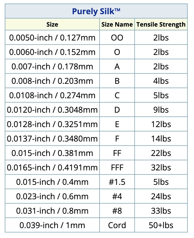
There are a few limiting factors for how small we could make this whole interface, starting with the capstan cable. We needed a thin cable that was also "floppy" enough to wrap around a capstan only a few millimeters thick. For the time being, we decided to use silk, as it has remarkable tensile strength without much deformation. I found a table of silk string sizes, and we ordered a spool of size FF silk as a starting point.
Week 2
We wanted to use the best available material for testing, so I underwent official training for the MarkForged Onyx printers in Bray Labs, and am now able to print there whenever.
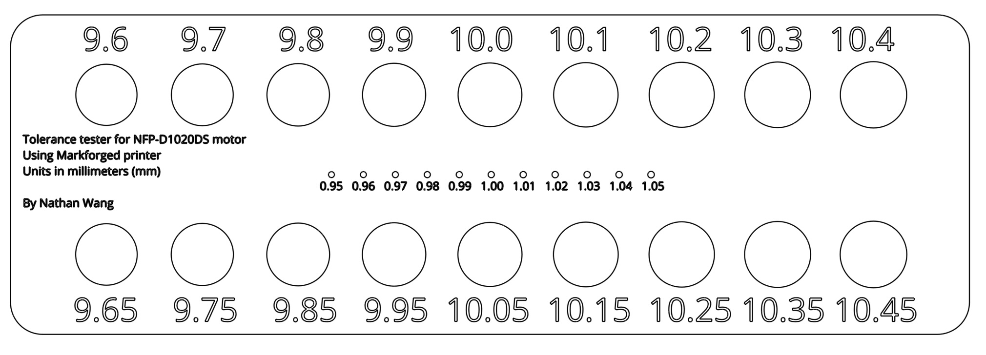
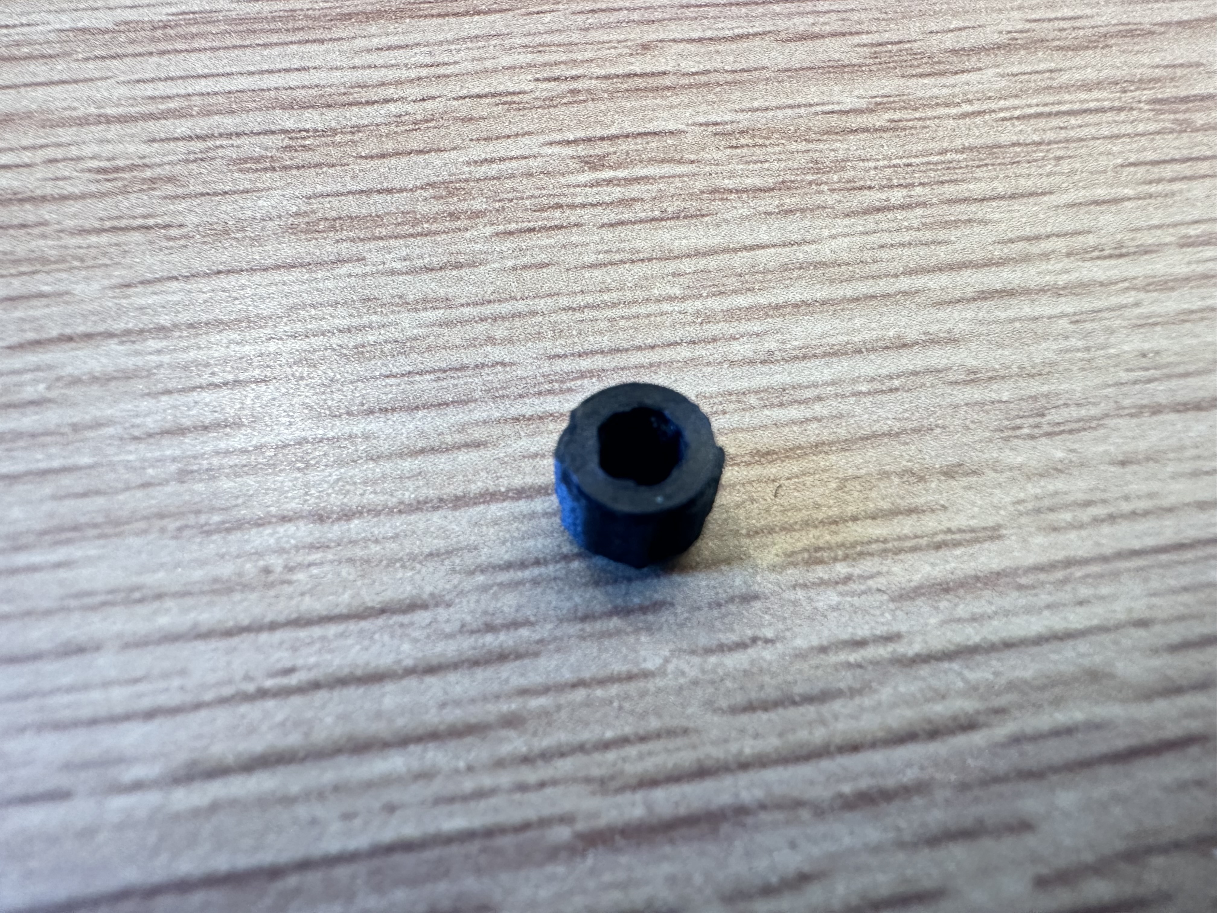
In order to keep the system as small as possible, the first question I tackled was how to connect to the motor shaft. Initially, I was thinking of directly attaching to the shaft using a thin 1mm hole. However, upon printing tolerance tests, it was quickly apparent that the printer could not create holes exact enough consistently.
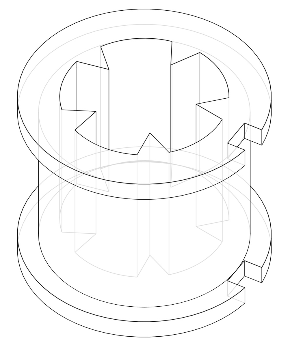
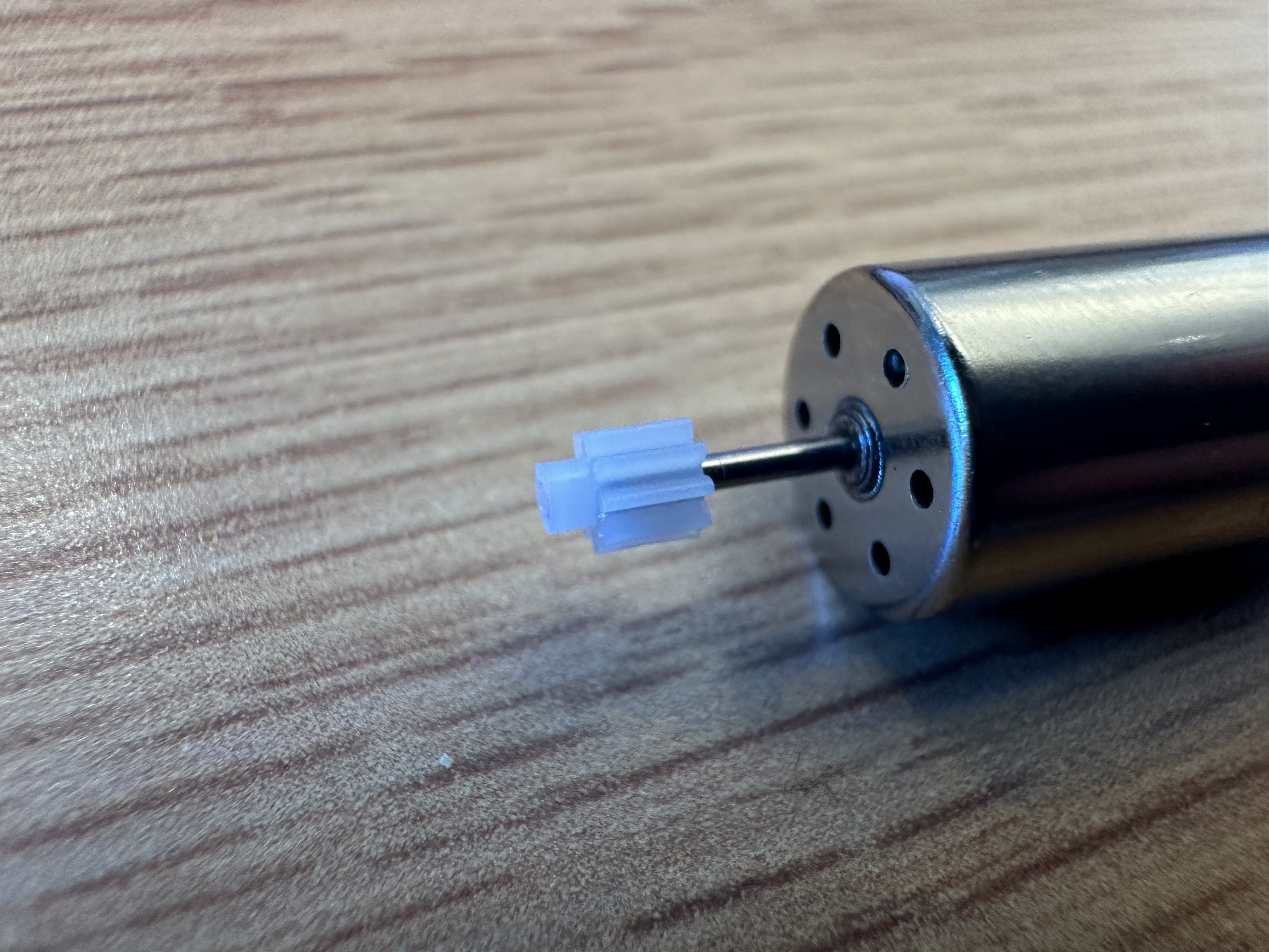
With this information, we decided to pivot to using the plastic gear that the motors come with as something for our adapter to grab onto. By using teeth to grab onto the gears, the design allows for high tolerances in fabrication due to the slight elasticity of thin plastic and its ability to fit itself around the gear.
The alignment worked pretty well when the part was printed out. There was definitely merit behind the idea of using teeth for alignment. However, the capstan was able to slip off the gear quite easily. Some creativity would be required to geometrically constrain the capstan onto the motor shaft.
Week 3
Upon realizing that we had a very limited number of the small white gears, we searched for reliable vendors selling something similar in bulk. We did not want to be constrained to using parts that were hard to get. We found a seller on eBay and placed an order, but the shipping estimate was much longer than we had hoped.
With nothing much left to do for the capstan until the new gears arrived, I decided to work on the motor mount. I wanted to design a mount that would clamp gently onto the motor body while also providing support to the far end of the motor shaft to avoid cantilevering. Leaving room for an encoder installation in the future was also a must.
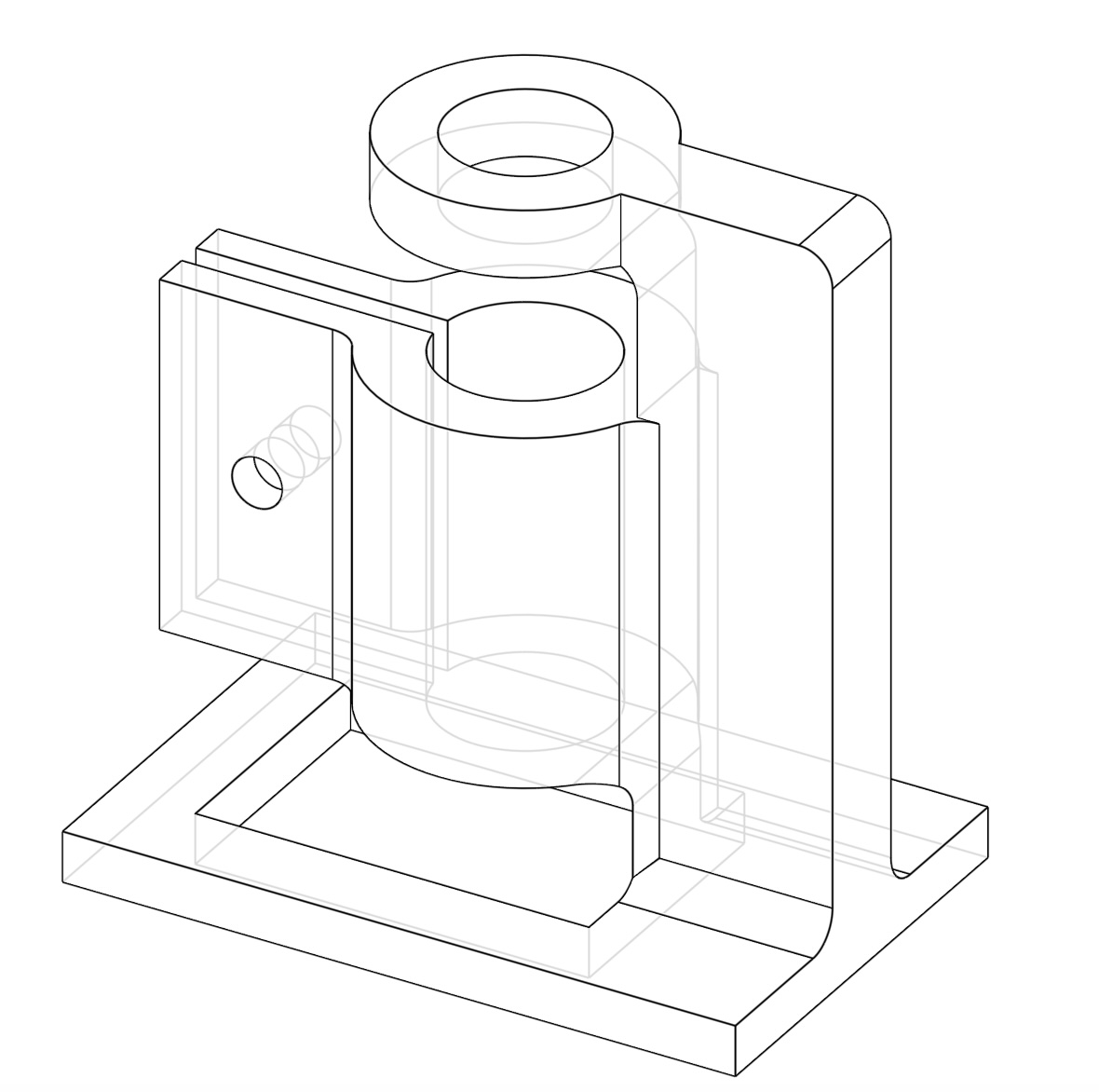
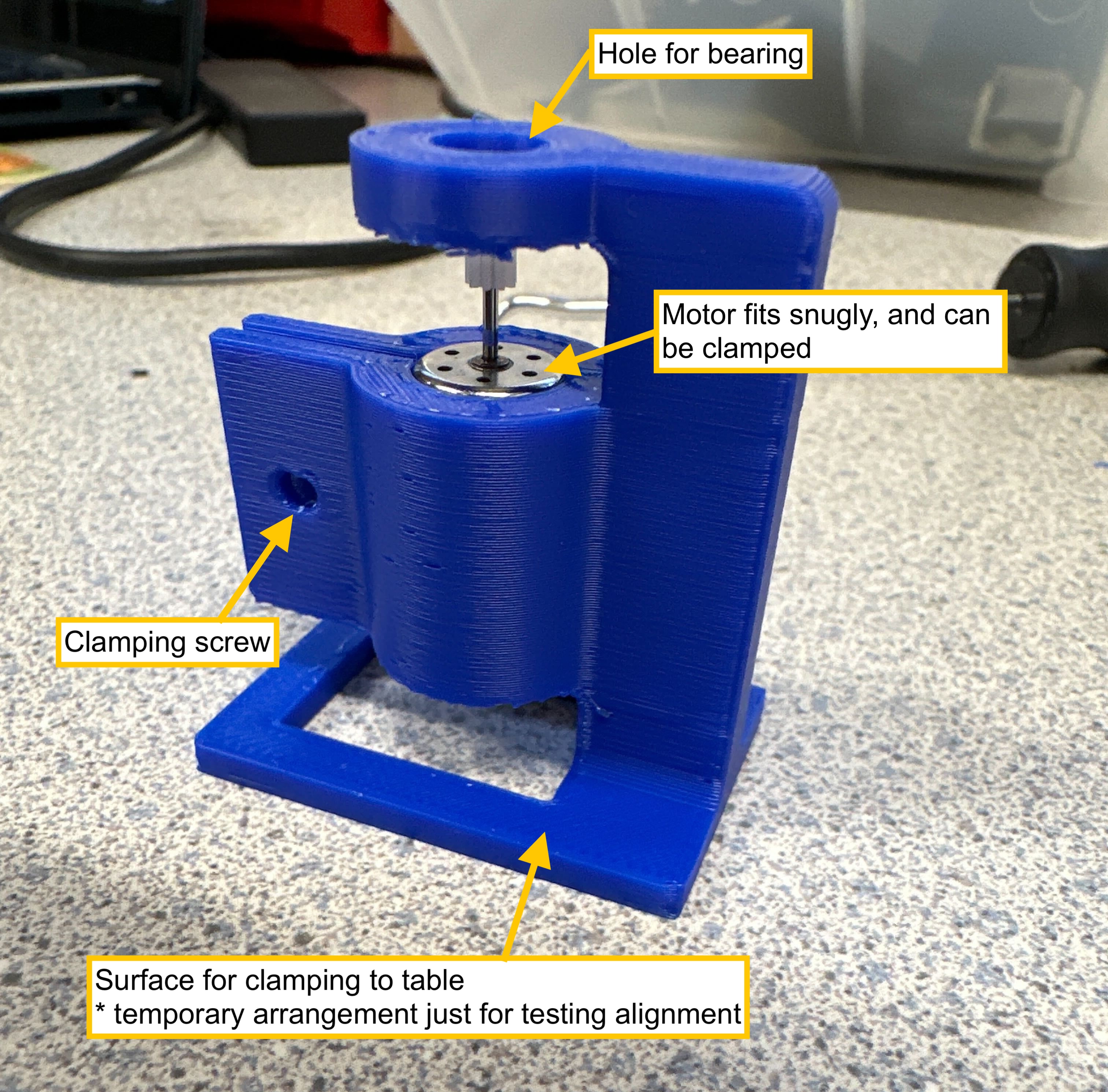
Below is the design I arrived at. The wide base is empty to allow for the motor to be pushed up into the clamp from below, along with the encoder. The hole on the top is designed for a 9mm OD bearing, which will be adapted to in the design of the capstan. Multiple copies of this were printed out, as I wanted to see if there were any materials that worked the best.
The motor fit snugly in the clamp. The design for the base may change in the future as we decide what exactly we want to attach the motor to, but for now the clamping mechanism and shaft support seem to be adequate.
Week 5
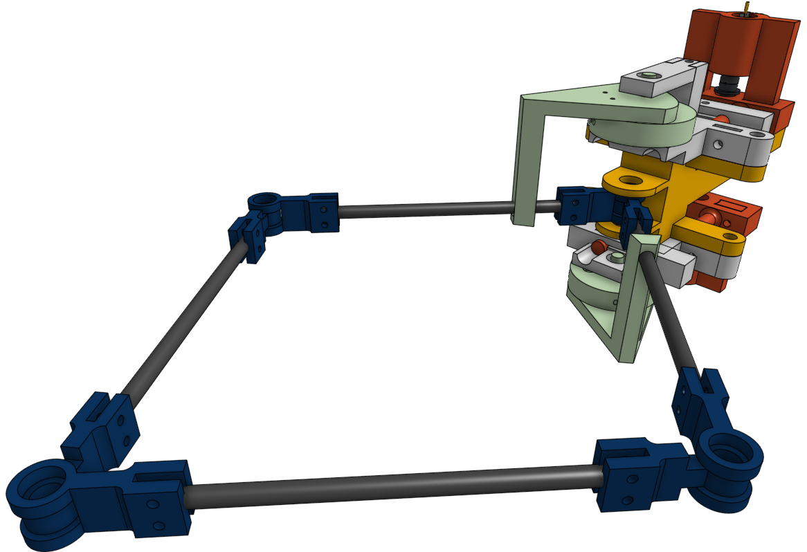
To test the capstan smoothness, I created a tensioning jig. The motor mount and wheel were mounted on cylindrical modules that slotted into the jig. This jig can be tensioned using the long bolt, which pushes the arms of the jig apart.
Week 6
In order to make assembly a bit easier, the motor encapsulation was modified to be a slide on. [WORK IN PROGRESS ENTRY]

